BRE Datsun 510


ABC Hobby BRE Datsun 510 #46 body on Tamiya M-05 chassis.

After smashing up the Honda S800 body too much, I got a replacement.  This is an ABC Hobby BRE Datsun 510, #46.  This one is closer to a 1/12 scale body, compared to the S800 and Mini bodies, which are 1/10 scale versions of smaller cars.

Brock Racing Enterprises (BRE) set up some Datsun 510’s for racing, and entered them in the 1971 and 1972 Trans-Am “2.5 Challenge” for smaller engined cars.  Datsun destroyed the competition both years (though Alfa tried to cheat to avoid their fate in 1971), and the series was shut down when the European manufacturers picked up their toys and went home crying.

The body shown here also comes with bumpers and better headlights, but I decided not to use any of them since I expected to beat it up racing anyway.  Unfortunately I must have scored the body when trimming the paint mask, because it almost immediately split right up the left front corner between the red and white areas.

Fitting the body over the wheels was a bit challenging, and required some creative trimming around the wheel wells to keep it from rubbing around corners.  Unfortunately the M-05 battery compartment pushes the battery wires into this body, which flexes it on whichever side the battery protrudes from.  It’s a tight fit, but it works.

Sakura S Zero

Sakura Zero S chassis with HPI Honda NSX GT body

In anticipation of On-Road racing at PT Raceway, I decided to get a second on road car so I could race in two classes instead of just one.  I chose the Sakura Zero S chassis from 3Racing because it looks very good for its price, it’s a kit, there are many replacement and hop-up parts available, and it gets good reviews.

The Sakura Zero S is an entry level version of the Sakura Zero chassis. The main differences are that the S version has plastic parts instead of aluminum; fiberglass instead of carbon fiber; gear diffs instead of ball diffs; and it costs about 1/3 as much.  It’s a 4 wheel drive touring car chassis with a twin horizontal plate design.

This was a very fun kit to put together.  Its plate chassis is very different than the other kits I’ve built recently: the Tamiya M05 and HPI Savage XS.  Unfortunately, the Sakura also suffered from Crappy Screw Syndrome, just like… well, apparently this is just like every RC kit everywhere.  This time, instead of starting out driving the 3mm screws straight in with a 2mm driver, I threaded every hold with a screw that had a larger 2.5mm head.  This destroyed my hands, but I stripped fewer screw heads (unfortunately more than zero). As much as I didn’t like the phillips head screws in the Tamiya kit… at least the heads didn’t strip easily.

Sakura Zero S chassis with HPI Honda NSX GT body

The chassis has very adjustable suspension geometry, but the stock dampers don’t allow unlimited adjustment of ride height. I doubt this will be a problem in the short term. It doesn’t look as durable as the M05, but it’s also not a giant block of plastic.  I think at the speeds I’ll be running at the track, it won’t matter.

Other than the screw heads, there are a few problems with the kit.  The first and most universally well known problem with the Zero S chassis is that the stock motor mount is inconvenient, because you can only access one of the motor screws by sticking your tool through a hole in your spur gear.  This is inconvenient with some pinion sizes, and impossible with smaller spurs.  There’s a vertical motor mount part available, but this requires you to also use a new top plate and flip your differentials to swap the side each belt runs on… and that causes your belt to run into your battery on the other side. This kit is not ideal if you’re planning on changing pinions often… but it’s still a lot better than changing pinions on the HPI Savage XS.

The other minor problem I have is that the turnbuckles seem to have undersized flats, making them difficult to turn without slipping.

For a body, I was in a hurry and couldn’t find anything I fell in love with, for sale at the same place as the chassis.  So, I settled for “acceptable and inexpensive” instead. This is an HPI Racing Honda NSX GT.  It retains a bit of the car’s distinct look, especially the air scoop on the rear roof.  Hopefully I won’t have any problem with traction roll, because I don’t think the scoop will last long if the car is upside down.

The body fits the chassis perfectly.  Figuring out where to drill the body mounting holes is a pain, though. You can’t drop the body onto the car and mark them until the posts are cut to approximately the right height, but you can’t cut the posts until the body is on the car to see where it sits.  I ended up measuring the body posts in relation to the center of the wheels, and transferring their locations onto the body using the center of the wheel cutouts as a reference point.  It worked, but it felt like there should be an easier way.

Since I’m going to race this instead of admire it on a shelf, I used the external headlight stickers instead of the internal light cans.  I think it’d look a lot better with the light cans… until I hit a wall and crack the body, in which case I’d rather have more room to repair it inside instead.

For electronics, I used what I had on hand: a 27T brushed motor and ESC I replaced in the RC10, and a Hobbyking Orange Rx Spektrum receiver.  I’ll start out with this slower setup, and once I like how I’m handling it (or once I burn out the motor) I’ll probably upgrade to 17.5T brushless. So far I don’t see hugely different times at the track between the three other cars I drive there (Tamiya M05 with stock 27T brushed; XXX-SCB with 17.5T brushless; RC10 with 17.5T brushless), so I expect the current limitation is my own driving skill more than the technology.

Unfortunately I couldn’t make it to the first on-road race day on December 1, and I won’t be able to make it on the 15th either. Maybe they’ll run on-road on the 22nd, but if not I can make it on the 29th.

XXX-SCB: New Body

Losi XXX-SCB with body painted by Alan Ferrency

After a summer of bashing the XXX-SCB in the yard, and then rolling it over trying to tune it for racing at the track, the original ready-to-run body was cracked at the front shock corner, and generally really beat up.  I ordered a new transparent body to paint up myself, and here’s the result.

I don’t like modern, garish complicated paint jobs very much, so I went for a cleaner, simpler look.  The general contours of the colors was lifted from a real Lucas Oil Offroad Series pro buggy, but I used yellow instead of white.  I got the numbers printed at the same time I made decals for the RC10, but the rest of the stickers are for manufacturers whose parts are on the car.  I’m not a huge fan of the “rolling billboard” livery look, so I didn’t cover every possible surface with advertising, but I think the limited use of stickers add to the scale look.

At this point I have the car handling really well on the carpet track, I just need to get out on race day and see if I can manage to not crash for 5 minutes in a row.

RC10: Viper Mk II Complete

Here is my completed RC10 body with livery based on a Viper Mk II from the modern Battlestar Galactica show.

I designed custom graphics using Inkscape.  I found information about the font used in the show on a Galactiguise post.  A semi-crippled version of the font is available for free download there.  After getting everything right, I sent my file to Cafe Press and had a transparent bumper sticker printed with my designs on it.

RC10 gold pan with Battlestar Galactica Viper Mk II livery.

The print quality is what you’d expect from an inkjet printer: it has high resolution, but a grainy quality where it’s mixing dots to get the color you’re looking for.  The bumper stickers are supposed to be waterproof and durable for outdoor use, so I expect this will work as well as any RC car stickers.

I recreated the 3rd squadron “VIGILANTES” seal for use on the nose. The rest of the markings are typical of a Mk II Viper, though not necessarily identical.

I also finally got around to building the wing. I don’t like the way wings look most of the time, so I kept this one transparent.  I don’t expect it’ll make any difference in performance on the relatively slow carpet track.

You can also barely see the new “stock” motor I installed.  Hopefully the sensor wire won’t get too botched up, hanging out like that.  I haven’t had a chance to get to the track to verify I’m using the right size pinion, yet.

HPI Savage Flux XS SS Initial Review

After building the Honda S800, I was itching for a kit that took a bit longer to build.  I also wanted to give the kids more opportunity to participate in the build and in driving the resulting car.  Ezra wanted a Monster Truck, so I searched for one available in kit form and found the HPI Savage Flux XS SS.

The HPI Savage is their 1/8 scale nitro powered monster truck.  “Flux” makes it electric.  “XS” makes it extra small, with the body being approximately 1/12th scale. “SS” is the Super Sport kit edition.

I finished building the truck, with intermittent help from the kids; but according to Ezra’s definition it isn’t a Monster Truck yet.  A monster truck has to be a truck, but it also has to have monsters on it.  We hoped to find some good stickers for this during the halloween season, but haven’t succeeded yet.

I haven’t driven the car very much yet, so this initial review will be primarily about the kit build itself.  It was definitely a more involved, slower build than the Tamiya M-05 chassis.  Some of this was the fact that it’s 4wd, some is because of the design, and some of it is because of frustration during the build. There are some parts of this kit’s design I really like, but other aspects are pretty bad.

The basic design is quite solid.  The first section of the build is putting together the front diff and suspension arms. The second part is the rear diff and suspension arms.  The front and rear half of the truck are nearly identical: the diffs and bulkheads are the same, and all 4 A-arms are interchangeable.  The main differences are the front and rear hubs (also identical side to side) and the bumpers. Overall this symmetric design makes it more convenient to deal with spare parts.

The front and rear are joined with a two part plastic center chassis that is reminiscent of the twin plate design used on the larger Savage.  The diff and motor are stuffed into it in a single piece, and the servo is buried in there somewhere as well.

One complaint I’ve heard about this truck is the difficulty of maintenance on various parts.  I think there is some truth to this: it’s a very tight truck, some parts are hard to get to, and most of the stock screws absolutely suck (more about that later).  But it’s not as bad as many would have you believe.  This is a lot more evident if you build the kit and see how things go together (and come apart).  You can remove the front and rear diffs for servicing with only a handful of screws.  The center diff and motor do make it a pain in the butt to change pinions often. They can be removed pretty easily; the problem is wedging them back into place with the front and rear dogbones where they need to be.

The absolute worst thing about this kit is the hardware.  Most of the screws are metric M3 with 2mm hex drive heads. The 2mm hex drive is simply too small for the screw material they chose.  The sockets can’t handle the torque required to drive the screws very far into fresh plastic.  I tried several different 2mm hex wrenches, and they all had the same problem: some of the sockets are oversize, and the screw material is soft, so the head ends up stripped.

I ended up stripping at least half a dozen screws during assembly, and had to extract several destroyed screws and replace them.  Luckily, the non-HPI replacement screws I bought work much better.  Several more screws are still stripped, but I managed to drive them all the way in, and hopefully I’ll never have to remove them.  The problem most kits have is accidentally stripping out the plastic.  These screws cause too many problems in the other direction.

For this body, the kids decided they wanted a light blue color, with a white roof and black trim.  They planned to add skull and crossbone and lightning stickers on it, but we haven’t found any reasonable options for either of these yet.

“But, that car isn’t blue,” you say.  An astute observation!  The only light blue Lexan paint I found was very old, and the can got me about 2 seconds of spray time before running out of pressure.  So now, the car has a light dusting of metallic silver-blue, and I filled out behind it with red.  It’s not totally horrible looking, but it was definitely not what we were aiming for.

This is the first time I’ve used Fasmask liquid masking for the interior of the body. The windows came with precut masks, but I masked the roof, bed, and lower edge of the truck.  The Fasmask worked pretty well, but I need to make a few changes next time.  Here are my newbie tips for using Fasmask:

  • Follow the directions when they say that multiple thick coats will make it easier to remove the masking material.
  • Don’t bother trying to paint the exact edges of the area you’re masking.  If you can do that, you should just paint the lexan paint on by hand instead.  Go over your lines far enough to ensure a thick layer where your design ends, and then cut the design into the mask.  This gives a much cleaner edge.
  • Don’t start masking if you’re in a hurry. It takes a long time for each coat to dry, and you need several of them. 
Looking on the Internet, I figured out how people test their maximum speed, for what it’s worth: strap on a portable GPS, and press Go.  I geared this truck down a bit, with the larger spur gear the truck comes with, and it’s being powered by a Duratrax Element (by Castle) 3900kv sensorless brushless setup.  With 6c NiMH batteries, I got up to 27mph in the alley behind the house.
This is no speed demon in its current form, but it’s still way faster than I should be letting the kids play with at this point, so I have no problem with that. 
Now we just need to go find some place to bash it before it starts snowing. 

RC10 Gold Pan: Viper Mk. II

I painted the original body for my RC10 day-glo orange, like they used to use for street maintenance in the mid 80’s.  It’s showing its age, with scratched paint all over the place, and cracks where it is most often stressed.  Also, it’s ugly.

It turns out that Team Associated still sells bodies for the original RC10.  Two different varieties, even.  So, when I ordered steering parts (that didn’t work) in August, I also ordered a new Viper body.

I already thought this buggy reminded me of the Viper Mk II from Battlestar Galactica. So, why not use a Viper-inspired paint job?

RC10 gold pan, new Viper body

I masked the windows and applied masking tape for stripes in the approximate locations of the red stripes on the Viper Mk II, and sprayed the rest white.  After removing the tape I sprayed red with another layer of white behind it.

I finished it with hand painted netting on the windows.

I learned a bit about masking: you need to be very careful about getting the edges of the mask to touch the car, or they don’t work.  Unfortunately the white overspray on the red portions don’t work that well as battle damage, yet, because the rest of the body looks so pristine.

I hope to get some decals printed with BSG viper logos.  I think that would add a lot to the look.

RC10 Gold Pan Renovation: Part 3, Steering

Flashback to late August:

After replacing the wheels on my RC10 gold pan buggy, it didn’t handle very well.  Considering the fact that the front wheels rubbed on the front a-arm at full steering travel, that should not have been surprising.  But I wanted to try reducing the steering travel to avoid rubbing, and see if that helped.

Unfortunately this didn’t work.  The steering linkage was plagued with problems.  The car had a wider turning radius in one direction than the other, the servo struggled, and there was a lot of play in the linkage.

After looking at the steering linkage enough times, I realized it pretty much sucked.  Plastic bell cranks ran directly on threaded screws for pivots without bearings; the servo saver was sloppy; and it had a bent wire linkage to the servo instead of a ball and socket linkage.

After doing some research at rc10talk.com, I learned that replacing the steering linkage with one that used bearings was common.  Most of the bell cranks that were used Back In The Day are no longer available.  However, Traxxas makes a bell crank set that’s a perfect fit.  Sweet!  Okay, well not perfect, but close enough.

As outlined here, you need to make shims to fit between the inside of a 3/16 bearing, and the 8-32 screw used as a pivot on the RC10.  I used some of the #8 washer/spacers used on the rear wheels, to ensure that the bearings spun freely instead of rubbing on the chassis.  Once you do this, the rest is easy: install the bell cranks and turnbuckles, and you’re good to go with identical steering geometry to the original.

This helped a lot: steering was faster and more responsive, and with the better turnbuckle linkage I could tune it a lot more finely than it was before.  Unfortunately there still just wasn’t enough travel, so I was still stuck.

I wanted to get new front hubs with more caster.  The original car has 25° for the shock travel angle, but the hubs push caster back to 10°.  I wanted to try 25° of caster, so I bought some RC10B4 caster blocks and hub carriers and associated gubbins.  Unfortunately I got the wrong king pins, and couldn’t assemble it.

Flashforward to late September:

RC10 with Traxxas bell cranks and wide track arms

I sat around not doing anything with the RC10 for a long time, but then I needed to order a replacement part for my Losi XXX-SCB.  So, I added my missing king pin (and screws) onto the order.  A-Main hobbies also carried some original RC10 swept-back front A arms, the “wide track” version in black; so I added those to the order as well.

Oh, I should also really replace all the transmission bushings with bearings, so let’s just throw those onto the order as well…

So on Tuesday night and Wednesday, I put it all the new parts on and rebuilt the shocks with heavier oil.  Here’s the result.

I had to remove the front anti-roll bar, because there is no mounting point for it on the wide track A-arms.  I calculated appropriate turnbuckle lengths to maintain the original geometry by extrapolating based on the increased A-arm length, but I expected to have to tweak them after driving it a bit.  Now, at extreme steering angles, the inside of the plastic hub is the first part to hit the A-arm; but at that point, you have plenty of turning going on, so it’s not a problem.

The shocks have never been completely disassembled and rebuilt, and they’re showing some wear inside.  It’s not ideal, but I’m going to live with them for now.  I completely cleaned the transmission parts using Simple Green in an ultrasonic cleaner, removed the bushings, and reassembled everything with the bearings.  Once every 30 years isn’t too often, is it?

On Wednesday night, I brought the car to the track and tried it out.  It worked a lot better than I expected: handling was great without me having to tweak anything at all.  I ran it through 2 battery packs, as much as I ran the Losi-SCB last night.  Apparently I’ve already bent one of the camber links, though; I guess I need Real Turnbuckles instead of threaded rod.

There was one problematic incident: I popped an E-clip on the transmission, and it blew the “bearing adapter”out the left side of the car. That’s weird.  There seems to be more slop on this shaft than it had with the bushings.  I used a new E-clip there, and it was fine for the rest of the night.  Consulting the assembly instructions didn’t show me any parts I was missing, so maybe the bearings aren’t the same dimension as the bushings they replaced.

Overall, I am now very happy with the way this car handles, indoors at least.  Unfortunately, whenever you pick the lowest hanging fruit, there’s always another one: it’s really slow, especially during acceleration. So now I’m thinking I might need to look into a “stock” (17.5 turn) brushless motor setup for it, to replace the brushed system it has now.  But I’m going to start by going to the J&C Hobbies flea market scheduled for next Sunday to see if I can find anything fun there.

Frank broke a part on his equally vintage Kyosho Optima on Wednesday night.  Don’t replace it! It’s a slippery slope, and a totally inefficient way to get a running buggy.  At this point it’s almost as easy  for me to list the parts I haven’t replaced, than those I have.  But several modifications ago I decided to “embrace the project” since it really is at least as fun as driving the resulting car.

RC10 Gold Pan Renovation: Part 2, wheels

After getting my RC10 back in service, it became apparent that I would need new tires some day.  The rear tires had very little tread or traction left, and the ground clearance was barely sufficient to run it on short grass.

Unfortunately, the original RC10 wheels are a small obsolete size, and modern tires aren’t available to fit them. My options seemed to be:

  • find vintage wheels and tires on ebay or other sources
  • buy JC Racing wheels that use standard buggy tires but allegedly fit on the original RC10
  • rebuild the rear end to fit modern buggy wheels

The JC Racing wheels look really nice, but they take a long time to ship from the UK, they’re expensive, and I’d need to salvage the wheels every time I replaced the tires since they cost so much.  Also, there isn’t nearly as much challenge involved in slapping new wheels on the car as there is with rebuilding the entire rear end.

There are many threads on various RC forums regarding the various ways you can adapt your gold pan RC10 to run modern 1/10 scale buggy wheels.  Unfortunately they tend to skimp on the details and expect you to figure stuff out yourself.  Truthfully, there are so many minor differences in early RC10 buggies that this might be the best bet.  But hopefully the story of what I did will help others who have the same problem.

I’ll deal with the front and rear wheels separately, because the front is much easier than the rear.

Front Wheels

Currently, RC10B4 wheels are still available, and they fit just fine on my original 3/16″ axles.  I started with DE Racing “Borrego” wheels for the B4 buggy, with 3/16″x3/8″ bearings to fit them.  I bought JConcepts Barcode front tires.

DE Racing Borrego front wheel, and original RC10 wheel

Overall, this setup mostly works, but it isn’t perfect.  The larger diameter wheel fits just fine, but the wheels are also wider. This causes the tire to rub on the front A-arm at full steering. This can be adjusted with servo travel on the transmitter, but it must increase your turning radius somewhat.

The Barcode tires were completely useless on grass, I may as well have been driving slicks.  Since my options were either to drive them for a few days and buy replacements, or save them for indoor driving and buy replacements, I opted to save the bar codes and buy even more wheels and tires.

I got Associated B4 wheels all around, hoping they might work slightly better than the DE Racing wheels.  For the front, I got Pro-Line 4 rib tires, a modern version of the original tires on the car.  Overall these worked very similarly to the bar codes: they’re a bit too wide, but otherwise they work fine.  They also don’t have great traction on the grass, but they have a heck of a lot more tread.

Rear Wheels

When I say “rear wheels” here, I really mean the entire rear end of the car.

There are two basic problems with using the original RC10 with newer wheels.  First, the old RC10 axle is weird. Instead of being a constant diameter 3/16″ axle as in the front, it has a fat section near the center of the car, tapering down to a narrower part where the wheel mounts.  The taper keeps the wheel from rubbing on the hub, but modern setups use a thick conical washer for this instead.  The second problem is the wheel offset: the old hubs don’t stick out as far, so modern wheels end up rubbing on the rear arms.

The basic solution to both of these problems is to replace the original hubs and axles with RC10B4 hubs and axles.  Unfortunately since you’re changing the hub location, this has a bit of a cascading effect and requires replacing quite a few parts.  For reference, I’ve found it useful to refer to the RC10B4 manual pdf (Google it if the link ends up broken), to find modern part numbers for the required replacement parts.

I opted to stick with the RC10B4 pin drive on the rear wheels for now, but it should be easy to use hex drive wheels with a hex adapter if the B4 wheels become unavailable.

I’ll try to detail everything I ended up actually using, without any of the extra parts I didn’t use; but I may forget something.  Most of these parts are shown on page 10 of the manual referenced above.

  • Associated 9584 rear hub carrier
  • (4) 3/16″ x 3/8″ bearings
  • Associated 9670 rear axle RTR
  • Associated 7368 3/16″ axle shims
  • (2) Associated 9671 B4 RTR dogbone
  • Associated 7377 axle spacers
  • Associated 7369 universal roll pins
  • Associated 5407 O-rings
  • Associated 9608/9608B wheel spacer
  • 4/40 threaded rod, for longer camber links
  • 8/32 wheel locknuts
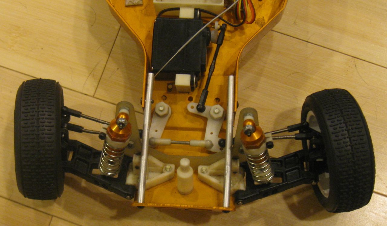
RC10 gold pan with RC10B4 rear hubs

The assembly is mostly straightforward.  Remove the old wheels, hub carriers, and camber links.  Save the ball link parts for use with the new hub carriers and camber links, and reassemble the hubs as shown in the manual above.

The B4 hub carriers have a narrower hinge pin hole, so open them up with a 1/8″ drill bit.  As long as your hinge pin is loose in the old A-arm, it doesn’t matter if it’s a bit tight in the new hub carrier.

Since the new hubs are offset farther out than the old ones, you need longer dog bones to compensate, or they will fall out when your suspension is fully extended.  Some people have replaced their dog bone linkage with CVD links, but I was not willing to risk getting the wrong part since it cost so much more than the dog bones.

On the original RC10, the rear dog bones are held in place using springs in the hubs with small nylon spacers on the differential side.  In modern cars, O-rings are used at both ends of the linkage. The B4 RTR dog bones are just at the limit of maximum workable length using a reasonable camber angle.  The important part to get these to fit correctly is to remove the nylon washer from the differential side of the link, before replacing it with a rubber O-ring.  When you’re finished, you should be able to bottom out the shocks before the dog bones bind up, but they won’t fall out going over jumps.

The wider hub offset also affects your camber settings.  You need longer camber links in order to maintain the original camber setting.  On my car, I had to increase the distance between the ball link ends to about 0.75″ in order to maintain a good camber setting.  This was enough of a change that I bought a long piece of threaded rod to build new camber links, rather than risking stripping the original plastic ball link ends by using them when they’re too loose.

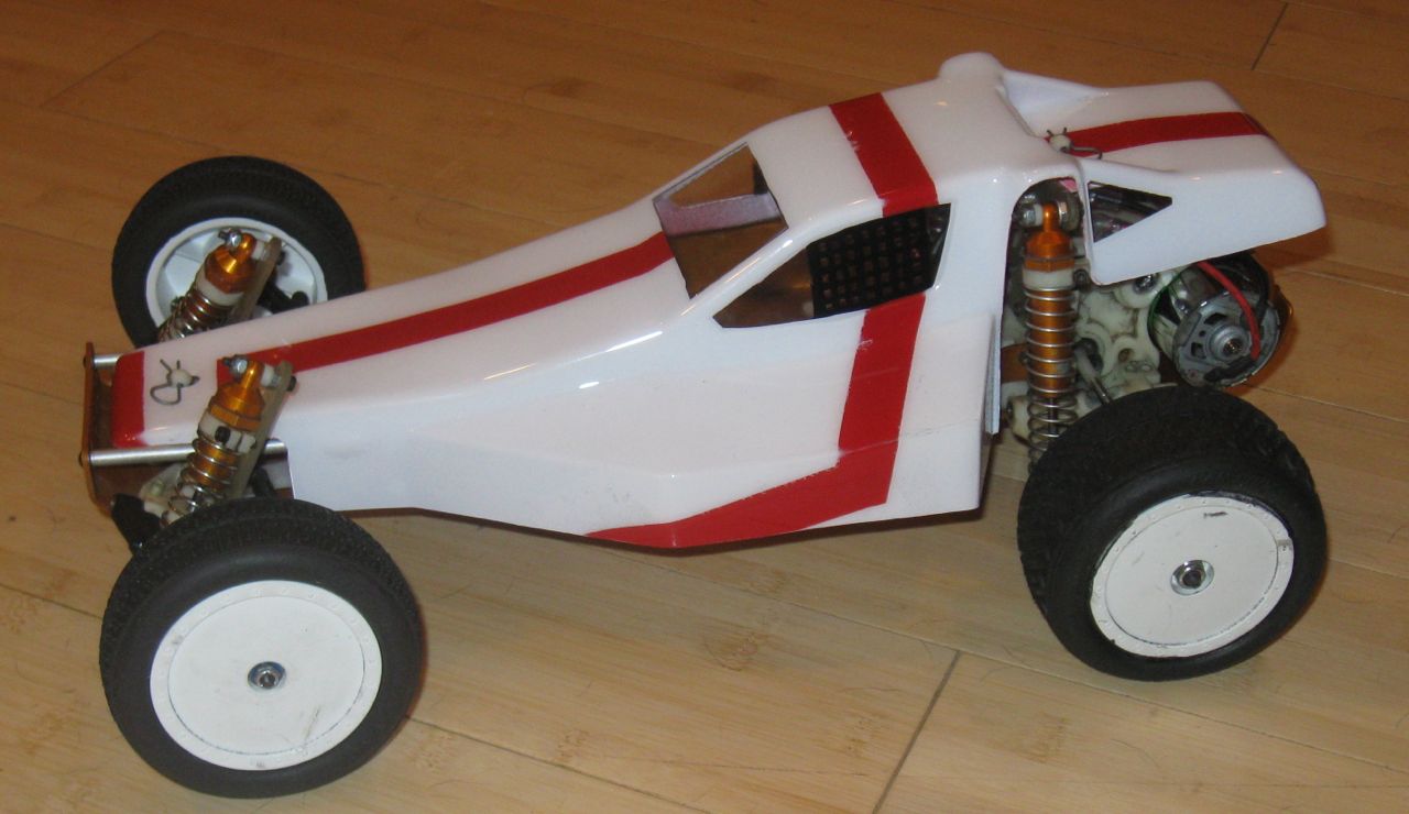
RC10 with B4 wheels and Traxxas/Pro-Line tires

I started with DE Racing Borrego wheels and Barcodes tires, just like in the front, but these tires don’t have any more traction when you put them on the rear wheels.

For my second attempt, I used Traxxas step pin tires and Associated B4 rear wheels.  These have a lot more traction on the grass than any of the other tires I’ve used on this buggy.  On the grass, the buggy used to oversteer a lot on corners, but now it pushes like crazy.  I like the overall look of the car with these tires.  The combination of pin and rib tires mirrors the car’s original look.

I may want to install a slightly smaller pinion to compensate for the larger wheel size, but otherwise I’m happy with these modifications. I should still be able to use the old wheels, so I can compare the handling to see if it’s any better now.

My original buggy had bushings throughout instead of bearings.  This project replaced almost half of the bushings with bearings, so I now have reduced friction as well as more modern wheels.

RC10 Gold Pan Renovation: Part 1

As I mentioned before, I had an Associated RC10 remote control buggy as a kid. It was a high quality car at the time, and took the hobby by storm when it was first released.  I wanted to get my car back into service after many years in storage, so here’s what I did.

RC10 gold pan, first release

This is an original “gold pan” model RC10, predating any stamps on the bottom of the chassis.  This dates it at about 1984 when the car was first released.

The first step in getting the car back into service was just to see if it even worked.  This was easier said than done, due to the state of the car’s electronics. The original radio was a wide-band aircraft radio (oops!), using frequencies that are no longer usable, so that had to be thrown out before it was even turned on.  The speed controller was a rheostat, and was mostly broken, so it also needed replacement.

The obsolete NiCd battery was so destroyed my dad didn’t even give it to me.  Unfortunately the original crosswise battery box mounting didn’t leave enough space for modern NiMh batteries.  In retrospect, I think I could’ve found a LiPo battery that would have fit, but instead I decided to remount the battery box lengthwise.

After a few attempts to make an adapter to mount the battery holder without drilling the chassis, I gave up and made a critical decision in the evolution of this car: I was not going to attempt to preserve the original buggy, but instead I would just make it work well using modern parts where necessary.

I’m keeping all the old parts, so it could be returned to close to its original state, but truthfully most of the parts I’m replacing for a reason, not just on a whim. The RC10 was a wicked good car in its day (see what I did there?), but mine was the very first version of the kit.  Changes were made to critical systems early in its life, and even when this car was original, people routinely replaced parts with better alternatives when possible.

So: To heck with it! I drilled and tapped 2 holes in the chassis to mount the battery holder.  Done!  One end of the battery now sticks in where the throttle servo used to be mounted, and the other end is held down by one of the two original battery holders.  A 6-cell NiMH pack fits perfectly, and I could probably run 7 cells if I found a hump pack instead of a long pack.  I haven’t made the switch to LiPo, but I’m sure something would fit here.

For the other parts, I got a Spektrum receiver and a brushed ESC.  I ripped out the throttle servo, speed controller, receiver, and receiver battery pack, and replaced them with the new parts.  The old Futaba servo needed a new connector, so I rewired it.  I also needed new bullet connectors on the motor, to replace the original Tamiya connector. I powered everything up, and… it worked!  Of course it did, why wouldn’t it work after replacing most of the electronics?

In the following weeks a few other problems cropped up.  The steering servo was slow and weak, so I replaced it with the Hitec seen above.  The motor ended up dying a slow death, probably because of worn brushes like my Losi motor (but after 28 years instead of 28 days). I replaced that with an Axial 27 turn motor to keep it at “stock” speed.

In the end, it’s more important for me to get enjoyment out of this buggy than to maintain its original state.  I get more enjoyment out of repairing and improving the buggy than from driving it when it’s in crappy condition.

Tamiya Honda S800

Before I got back into driving RC cars, I had spent a lot of time playing Forza 3 and Forza 4, on-road circuit racing games on the Xbox 360.  Although I had only ever driven off-road RC cars previously, my experience with Forza made me interested in on-road RC cars as well.  I’m interested almost exclusively in smaller vintage cars (old cars that aren’t muscle cars).  I also had fond memories of kit building, and my purchase of the ready-to-run Losi buggy made me wish I had purchased a kit instead.

So, put it all together and I ended up with an obvious conclusion: just before vacation last month, I ordered a Tamiya 1/10 scale RC Honda S800 kit, which uses Tamiya’s M-05 FWD on-road chassis (unlike the original’s RWD drivetrain).

The kit went together quickly; almost too quickly to be satisfying.  I had the mechanics and electronics done in a few evenings, and didn’t run into any problems with the build.  I wanted to keep things simple and inexpensive the first time around, so the only hop-up part I used during the initial build was a bearing kit. I remember how much of a pain in the butt it is to add bearings after the car is complete.

The decal sheet that comes with the car allows you to reconstruct the S800’s most famous racing livery: #25, currently on display at the Honda Collection Hall at the Twin Ring Motegi circuit.  I painted it using Tamiya Yellow polycarbonate paint, with a coat of Pactra white behind it.  The white really helped the yellow shine through, and the result is almost too bright compared to the historical car it’s patterned after.

There are a lot of decals (really just stickers), and they took a long time to apply.  Each one needed to be cut out individually before being applied appropriately.  It ended up being tedious, but not as difficult as I feared to get the decals in the right place without any bubbles.  The end result was definitely worth the work!  This is a really beautiful car.

Comparing the car to pictures of the original, the only places where the decals are at all different is where the original car has holes in the body, but the model has decals.  Specifically, in the rear lower corners there are round decals with an odd shape that doesn’t make much sense, which correspond to holes in the body on the original car.  It’s almost as if the decal designer looked at one picture of the car and made a decal of what could be seen through the hole from his vantage point.

The only complaint I have about the decals is with the ones that are supposed to go over curved surfaces, such as the chromed fender lines and the trunk hinges.  These don’t stick well enough to stay on the car (as seen in the image above, if you know what to look for).  Since they’re simple single-colored decals, I will probably take them off and paint the lines instead.

I had one problem with the car after it was assembled with the body in place.  The rear end of the front fender was very close to the front wheel, and it would catch on the wheel during turns.  This suboptimal body position can be seen in these images. I fixed this by raising the rear body clips so the body was higher in the rear, and angled away from the front tire, and I haven’t had any problems since. It looks a bit better than the “low rider”look the rear has with the stock body position.

The Honda S800 is a really interesting car. It looks to me like it’s basically a clone of a contemporary MG roadster, similar to Honda’s N600 clone of the Mini.

Today I had my first chance to really drive the car instead of just puttering around in the alley.  It’s so nice looking that I’ve been afraid to scratch it up. But I built an RC model and not a plastic display kit for a reason, so to heck with it.  The kids wanted to ride bikes and scooters in the flat walkway in front of the church across the street, so I brought my car as well.

Not surprisingly, this car handles extremely differently than the buggies I’m used to driving off-road.  On the flat, with no obstacles to run into (and using the stock motor and a 6 cell NiMH pack) I was 100% unable to roll the car over in a corner.  It pushed into corners at speed, which is expected for a front wheel drive, but the rear end cut loose long before the car felt likely to roll.  This FWD chassis is extremely stable, with a very low center of gravity.

The stock M-05 chassis comes with friction dampers instead of oil-filled shocks.  I didn’t want to replace these until I experienced driving without them, but it was quickly obvious why oil dampers are necessary.  The body bounced around a lot when cornering, in a very unnatural and unpredictable way.  

After a bit of driving around aimlessly, I set up cones and Ezra rode his bike while I raced him with the RC car.  Flat-out, he was no match for the stock motor, but around the corners his massive size made him very hard to pass safely.  On 3 occasions, I ended up in front of him and he ran over the car.  Oops!  It survived with only scratches (on the inside of the body), so no harm done. I also hit his rear tire a couple of times, which instantly flipped the car due to the tire’s upforce.

At this point, I’ve gotten over my fear of scratching the car; but I’ll probably touch up the paint and apply electrical tape where it’s most likely to hit the chassis. I’m also a lot more interested in driving it than I was before.  I’ve ordered some 3Racing dampers, which are far cheaper than the Tamiya hop-up part.  Other than that, I plan to leave it stock until something breaks or wears out, just as I’m doing with my other cars.