
The Line 6 FBV2 is a control pedal for use with older Line 6 amplifiers and effects processors. I bought it to use with our Line 6 Amplifi 75 guitar amplifier. Unfortunately, it isn’t compatible with this newer amplifier, so it’s been sitting on the shelf for over a year.
After starting to play with an Arduino development kit recently, I decided it was time to revisit the FBV2 pedal to see if I could make it do what I wanted.
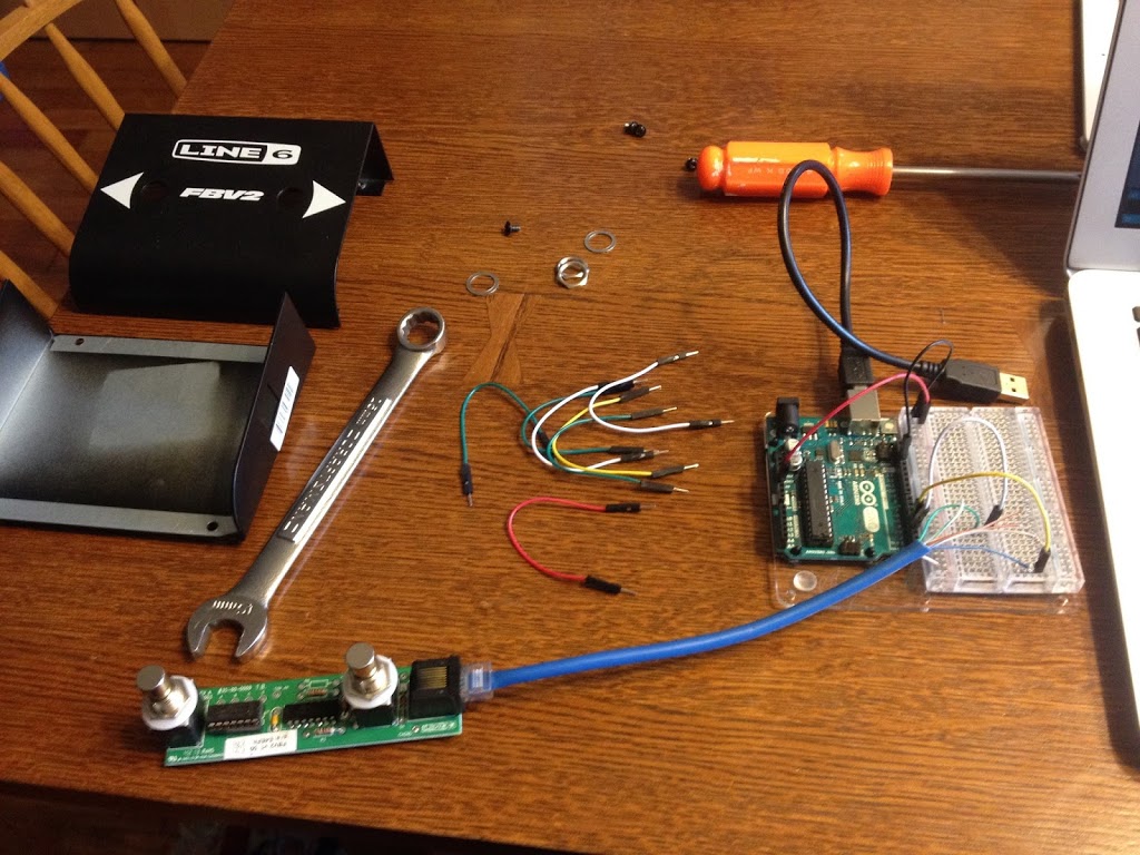
A quick disassembly revealed a single small circuit board with only 2 ICs and a handful of other components. This looked like it might be easy to reverse engineer and see how it worked.
 |
| Line 6 FBV2 circuit diagram, approximately. |
I followed the traces from the 8-pin RJ45 connector to the ICs and switches on the board, and drew a rough circuit diagram. Looking up the part numbers, I found an inverter and a microcontroller. The pinout from these parts let me identify the transmit, receive, and power pins on the connector.
The microcontroller is branded NXP, made by Phillips: P87LPC760. This doesn’t seem to be made anymore, so it seems not worth getting a replacement and programmer for it. My first idea for making this usable was to read the output from this device and convert it into something my Amplifi 75 can understand.
I hacked apart a spare ethernet cable to use its RJ-45 connector, and connected the FBV2’s transmit, receive, and power pins to my Arduino’s breadboard.
 |
| FBV2 disassembled and attached to the Arduino |
I had heard the Line 6 devices used MIDI, so I approached this as if it were a MIDI device. I didn’t bother building an electrically correct MIDI interface, which requires an optoisolator, because this device was being powered by the Arduino board (via my laptop), so there was no danger of a ground loop. Besides, this device should already have an optoisolator if it needed one, but it didn’t; so how important could it be?
I wrote a sketch using the SoftwareSerial library to interpret the output of the FBV2 as a MIDI stream: 31250 baud, with the default start/stop bit options. I mirrored the bytes over the USB serial port to the serial debugger in the Arduino IDE to inspect the byte sequences emitted by the FBV2 when the left and right buttons were pressed.
After a bit of fiddling, I was able to read the output. There were 2 basic data sequences:
- Left button: F0 03 81 67 01 F0 03 81 67 00
- Right button: F0 03 81 20 01 F0 03 81 20 00
These certainly seemed like MIDI sequences, but they weren’t quite right:
- F0: System Exclusive. This is typically followed by a byte sequence terminated by F7. I don’t see that, so I though perhaps the byte stream was automatically terminated by a control byte (<= 128 decimal).
- 03: At first I assumed this was the only data associated with the System Exclusive event; but, see below.
- 81 67 01: This is a Note Off event on channel 2; note 67, velocity 1.
- 81 67 00: Note Off, channel 2; note 67, velocity 0.
- 81 20 01: Note Off, channel 2; note 20, velocity 1.
- 81 20 00: Note Off, channel 2; note 20, velocity 0.
This was all very hopeful, but eventually I realized it may not be important what this device outputs. Instead of converting this output to whatever the Amplifi 75 needs, maybe it would be better to replace the microcontroller with something a bit more accessible, and just program it to output what I needed instead.
My next few lines of inquiry weren’t fruitful, but I have a plan for what to try next.
I decided to pop out the microcontroller, which was helpfully mounted in a socket, and attach a few Arduino IO pins directly to the microcontroller outputs. This effectively replaces the FBV2’s brain with my Arduino, allowing me to program it to output whatever I want.
I wrote scripts to test a huge variety of MIDI control sequences: Control Change and Program Change events on all different channels with different controls and values, and the original MIDI-like sequences produced by the FBV2 pedal. Nothing seemed to be recognized by the Amplifi 75.
What I really need is a pedal compatible with the Amplifi that I can reverse engineer and see how it works. But if I had that, I wouldn’t need to make the FBV2 work, and there would be no point to completing the project.
It got late enough that I tore everything down and put it away.
Then, after a bit more searching online, I found some information that will give me a new start. A company called VLoTech created a github project that reads and writes FBV pedal board data, for the larger FBV pedal boards that are compatible with the Amplifi 75.
This project showed me that the F0 03 sequence is more likely to be a byte count for the subsequent commands.
I also realized that I didn’t measure any timing information from the FBV2 when I read its data sequences. It may be that the F0 03 81 67 01 and F0 03 81 67 01
sequences are “on” and “off” events that need a time delay between them in order to have an effect on the target device.
Next time I pick this up, hopefully later this week, I plan to try some of the other byte sequences documented in the fbv_tools project.
To be continued…