I’ve started looking into the Line6 FBV protocol again, after letting it sit for a year. This time, I had another Line6 pedal that is compatible with the Amplifi. By observing serial traffic between the pedal and amp, I was able to emulate the basic functionality of the pedal using an Arduino.
Hardware
I am vague in this section, because I do not know if the circuits I built are truly safe for the Amplifi hardware. I didn’t have any problems with the amp, but I did generate enough electrical problems via USB to cause my laptop to spontaneously reboot several times… that can’t be good, right? Any attempts to mess with your hardware will probably void your warranty, and a mistake could blow up your amp or burn your house down. You have been warned.
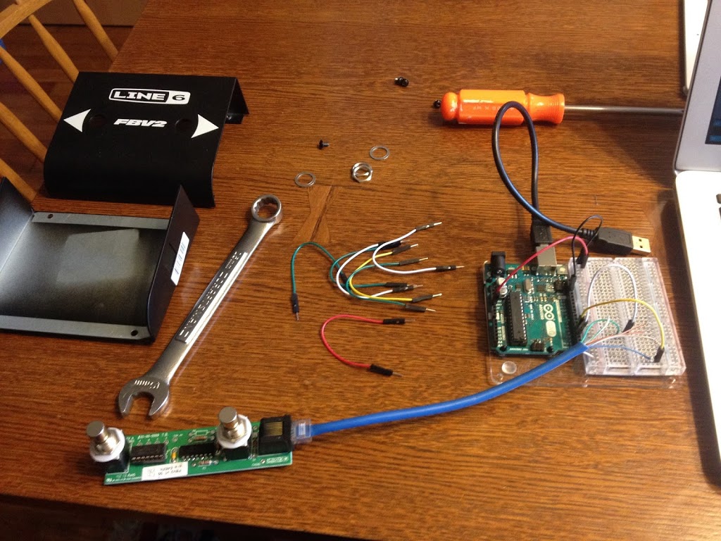
I used the same input/output circuit found on the FBV2 pedal. Sending data to the Amplifi did not work without both of the balanced signals on the cable. I believe this may be using RS-422 signaling, which requires that differential input. If so, a proper RS-422 chip might work better than the Schmitt triggers, but I haven’t tested it.
The serial specifications are the same as I used on the FBV2, and the same as MIDI uses: 31250 baud, 8N1. I used a higher serial speed for USB debugging channels, to reduce the chance of interrupting an incoming byte.
I assumed the connector wiring was the same as on the FBV2 pedal, and verified this is the case. However, the amp supplies far more than 5v, and the voltage will need to be regulated to be compatible with a 5v or 3.3v Arduino.
On the Arduino side, listening to both sides of an amp/pedal conversation, USB debugging, and controlling an LCD and buttons all at the same time was much easier using an Arduino Mega, which has multiple hardware serial ports. I wasn’t able to get SoftwareSerial or AltSoftSerial to do what I needed here.
I used an Adafruit character display I2C backpack with four on-board buttons to mock up a user interface. I can’t find this board for sale anymore on adafruit.com, so I’m glad I got an extra.
Protocol
The data sent between amp and pedal is sent in packets of the same basic format, and it matches what I found on the FBV2: “F0” followed by a length byte, and that many bytes of data. The interesting parts are the messages those packets can contain.
By recording the traffic between the amp and pedal while interacting with the pedal, I was able to identify many of the features of the communication protocol. However, there are also spontaneous handshake packets sent between the devices, and I have no clue what they’re for.
The messages themselves start with one byte that identifies the type of message, followed by message-specific data. Messages sent from Amp to Pedal had message IDs with the high bit off (0x00-0x7F), and messages from Pedal to Amp had IDs with the high bit on (0x80-0xFF).
Here are the message IDs I have identified, with my hypothesis as to what each one is used for. I made up all the message names based on what I think they’re for.
01 00
Every ~100ms, the amp emits this Heartbeat message, and the pedal emits a standard response (80, see below). I don’t know what this is for, but I assume it’s a heartbeat so the amp knows the pedal is still connected.
04 NN BB
I call this the LED message, because when it is sent, the pedal turns an LED on or off. NN specifies which LED is changing state, and BB is 00 for “off” or 01 for “on.” Values of NN I have observed:
- 61: Tempo. The amp flashes an LED on and off to mark the current “tap” tempo for effects.
- 20, 30, 40, 50: Patch LED A, B, C, D
- 21, 31, 41, 51: Unknown.
- 02, 03: Unknown; Wah/Vol LED, maybe?
When patches are changed by the pedal, the amp responds with a set of messages to update the pedal state for the new patch. Included are an LED message for each Patch LED, configuring its state, as well as some of the other unknown LED numbers.
08 C1 C2 C3 C4
The Small Display message sends 4 ASCII characters. When the amp is in Play mode, a message is sent whenever the patch changes, with the characters representing the bank and patch, such as ” 01A”. When the amp is in Tuning mode, this displays the note the amp thinks you’re playing, whenever it changes.
10 NN DD C1..C16
The Large Display message sends a longer text message to be displayed on the pedal. In practice, I have only observed messages with NN=00 and DD=10, followed by 16 (0x10) bytes of ASCII data. I am guessing DD is a byte count. NN might be a line number if the target device has a multi-line display, but I don’t know of any such device.
In Play mode, the amp sends the patch name in this message whenever the patch is changed. In tuning mode, the amp sends a string of characters that visually depicts how far off-pitch you are from the note sent in the Small Display message.
For example, when the note is perfectly tuned, it displays:
I---- ** ----I
When the note is off-pitch, it uses > < arrows to point which way to tune the string.
80 00 02 00 01 01 00
Message 80 with this specific byte sequence is sent by the pedal in response to each Heartbeat message it receives. I don’t know what the byte sequence represents, and it doesn’t seem to change depending on the state of the pedal’s buttons or LEDs. It may be a device-specific ID or some other kind of identifying information.
If I remember correctly, I found the amp starts to spam packets at the pedal when the pedal stops responding to heartbeats. It was easy enough to add a response handler for this, so I did.
81 NN BB
The pedal sends this Button Press message whenever a button on the pedal is pressed or released. NN represents the button number, and matches the NN sent in the LED message response: 20, 30, 40, and 50 are used for buttons A, B, C, and D. BB is 01 when the button is pressed and 00 when it is released.
The “tap for tempo” and “tune” features are implemented in the amp, not in the pedal. The pedal tells the amp when buttons are being pressed, and the amp tells the pedal what to display; it’s up to the amp to interpret the button presses as a patch change, tempo change, or tuning request. This makes development of the pedal software much simpler, and allows the amp to change its features in firmware without requiring a new pedal.
82 NN VV
The Expression message is sent whenever the pedal’s expression pedal changes position. NN has always been 0 in the messages I observed, but it probably denotes which expression pedal is being adjusted, in cases where more than one expression pedal is supported. VV is the value of the expression pedal: 0-127.
Startup, Patch Change, Mode Change
The pedal powers up when it is connected to the amp, and after a brief pause sends a few startup packets. In full packet form, the pedal sends:
f0 02 90 00
f0 02 30 08
Each line is one packet containing a message of length 2. The first one is message 90, value 0; the second one is message 30, value 08. This is the only case I’ve seen when the pedal sent a message without the high bit set. Either my interpretation of the message ID high bit isn’t correct, or I did not read the packet data correctly. I have no idea what these messages mean.
In response, the amp sends these two packets:
f0 01 40
f0 03 31 01 16
I don’t know if this startup sequence varies depending on the hardware involved, but it doesn’t seem to change depending on the device state.
Then, the amp sends packets containing a complete set of state to the pedal: Small Display, Large Display, and an LED message for each LED. The pedal only needs to remember these values and only change its LED and display when new settings are received from the amp.
Whenever the pedal sends button presses that are interpreted as a patch change by the amp, the amp replies with a complete state set, just as when the pedal starts up.
If the pedal user presses the button corresponding to the currently selected patch, the amp interprets this as a tempo change. Shortly after, the tempo LED messages will start arriving at the updated rate.
If the pedal user presses the “tuning” button combination, the amp enters Tuning mode. In Tuning mode, the amp sends Small Display and Large Display messages in real time as the user tunes their guitar. Further button presses reset to Play mode.
The future…
Before I left for vacation in August, I made plans for a few devices. These plans are on hold until I get another flash of inspiration, unfortunately.
First, I plan to replace the microcontroller in my FBV2 pedal with an ATTiny85 running emulation software that implements the two FBV2 buttons as “next patch” and “previous patch.” It listens to the incoming packets to determine the current patch, and calculates the button value to send for the left and right buttons based on the current patch. I got as far as emulating this behavior on the Arduino Mega, but didn’t successfully emit messages from the ATTiny.
The ATTiny is inexpensive and small, but unfortunately its limited feature set makes debugging very challenging. I may have to build an amp emulator with the Arduino Mega, just to debug the pedal emulator running on ATTiny…
My second project was a full 4-button pedal with expression. I mocked up all of the required functionality on the Arduino Mega, using the Adafruit LCD character/button shield. I will replace the on-board buttons with beefy pedal switches. Tempo will be marked by changing the LCD backlight color, and all tuning and patch names are displayed.
When I was working on this more actively, I thought I might be missing a large chunk of the FBV Mkii controller’s functionality: MIDI over USB. Thinking about it again, I’m not so sure. It feels like it would be a lot easier to implement MIDI in the device driver rather than in the pedal hardware. Maybe the USB port is connected to the same internal serial lines as the RJ-45 connector, and the device’s drivers convert the simple button press messages into MIDI messages before they make it to userspace?
This is a fun project… sometimes. The rest of the time, I don’t work on it, because I’m doing something I need to do, or something fun, instead.